Pipe Notching and Saddle Cuts: A Fabricator's Complete Guide

A pipe notching calculator gives you the exact curved cut profile — called a saddle cut or fish mouth cut — that the end of a branch pipe must follow to sit flush against a larger main pipe. Get this profile right and you get a tight, weld-ready joint with minimal gap. Get it wrong and you spend an hour grinding, or worse, you weld over a gap and compromise the joint.
Key Facts
- Formula (90°): z(θ) = r_main − √(r_main² − (r_branch × cos θ)²)
- Template width: π × branch OD (full branch circumference)
- Standard: IS 1978 — governs OD tolerances for structural tubes
- Tool: Free Pipe Notching Calculator →
What Is a Saddle Cut and Why It Matters
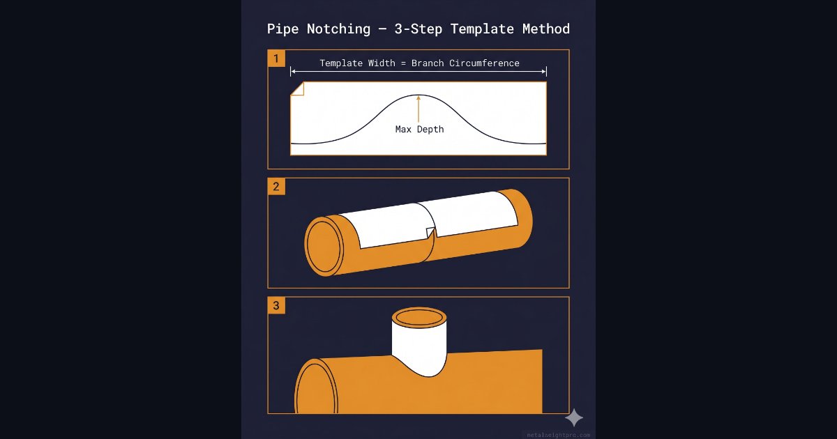
When a branch pipe meets a main pipe at any angle, cutting the branch end flat leaves large gaps on either side that are impossible to weld cleanly. The saddle cut profiles the branch end so that every point around its circumference lies exactly on the surface of the main pipe.
At a 90° joint, the saddle profile is symmetrical: it reaches its deepest point at the crown — directly over the main pipe centreline — and rises back to zero at the flanks. At non-90° angles, the profile becomes asymmetrical and the template shifts along its length accordingly.
In structural fabrication — handrail posts, pipe rack branches, tube frame joints — an unsupported weld gap of more than 1.5mm is a reject condition on most QA inspection sheets. A correctly generated saddle cut template eliminates that gap without hand-grinding for fit-up.
The Saddle Cut Formula Explained
For a 90° branch-to-main intersection, the notch depth at any point around the branch circumference is:
z(θ) = r_main − √(r_main² − (r_branch × cos θ)²)
Where z(θ) is the notch depth in mm at angle θ, r_main is the radius of the main pipe (OD ÷ 2), r_branch is the radius of the branch pipe (OD ÷ 2), and θ runs from 0° at the crown to 90° at the flank.
At θ = 0°, cos θ = 1, so z = r_main − √(r_main² − r_branch²) — this is the maximum notch depth. At θ = 90°, cos θ = 0, so z = 0 — the branch sits flush with the main pipe at its sides.
For angles other than 90°, the generalised formula is:
z(θ) = r_main / sin(α) − √(r_main² − (r_branch × cos θ × sin(α))²) / sin(α)
Where α is the intersection angle. At 45°, the notch depths increase and the profile becomes asymmetrical.
Worked Example: 60.3mm Branch on 88.9mm Main Pipe at 90°
On a pipe rack structure I fabricated recently, the joints used Tata Structura CHS 60.3×3.2mm branch pipes meeting APL Apollo CHS 88.9×4.0mm main pipes at 90°. Here is the complete calculation.
Given: Main pipe OD = 88.9mm → r_main = 44.45mm. Branch pipe OD = 60.3mm → r_branch = 30.15mm. Angle = 90°.
Maximum notch depth (at θ = 0°):
z = 44.45 − √(44.45² − 30.15²) = 44.45 − √(1975.8 − 909.0) = 44.45 − √1066.8 = 44.45 − 32.66 = 11.79mm
Template width: π × 60.3 = 189.4mm
| θ (degrees) | Arc position from centre (mm) | Notch depth z (mm) |
|---|---|---|
| 0° | 0.0 | 11.79 |
| 15° | 7.9 | 11.02 |
| 30° | 15.7 | 8.87 |
| 45° | 23.6 | 6.09 |
| 60° | 31.4 | 3.27 |
| 75° | 39.3 | 0.84 |
| 90° | 47.1 | 0.00 |
Arc position = (θ / 360°) × π × 60.3. The template is symmetrical — mirror these 7 points across the full 360°. Total template width = 189.4mm.
Generate this template automatically with the free Pipe Notching Calculator → — enter the two pipe ODs and join angle to get a printable PDF profile.
Non-90° Angles — How the Saddle Profile Changes
At 45°, the maximum notch depth increases significantly — the branch cuts deeper into the main pipe on the acute side — and the profile is no longer symmetrical. On site you will hear this called a "kati wali nali" — a pipe cut at an angle. The calculation is the same, but always enter the acute angle between the pipe axes. If the pipes form a 60°/120° pair, enter 60°.
Below 30° intersection angle, the notch depth on the acute side can exceed the branch pipe radius — a geometrically impossible joint for welding. The practical minimum for a saddle-cut pipe joint is 30°.
How to Lay Out and Cut the Template on the Pipe
Print the template at exactly 100% scale — set your PDF viewer to "Actual size" before printing. Verify the printed strip width against the branch pipe circumference with a tape. They must match within 1mm.
- Cut the paper strip to exact width (branch OD × π). Trim any white border.
- Wrap it around the branch pipe end. Align the strip seam to the pipe weld seam if present. Fix with two small pieces of masking tape.
- Score along the curve profile with a fine metal scriber. Press firmly to mark the pipe surface.
- Remove the template. The scribed line is your cut guide.
- Cut 0.5mm outside the line with an angle grinder and 1.6mm disc. Finish to the line with a 40-grit flap disc.
- Dry-fit against the main pipe. Joint gap should be under 1.5mm around the full perimeter.
IS 1978 specifies OD tolerances of ±1% for structural seamless tubes. On a 60.3mm OD pipe, that is ±0.6mm. For critical weld joints, measure the actual OD with a calliper and enter that exact value — not the nominal OD.
Common Mistakes That Ruin the Fit-Up
Using nominal bore instead of OD. A 2-inch pipe is not 60mm — its OD under IS 1239 is 60.3mm and nominal bore is 50mm. Entering 50 instead of 60.3 gives a wrong template every time.
Print scaling. Most PDF viewers default to "fit to page," which scales the template down. The result is a template that is narrower than the pipe circumference and the profile shifts off-centre.
Ignoring root gap for TIG welding. For thin-wall tube under 2.5mm being TIG welded with a deliberate root gap, the effective cut line moves outward by half the root gap. For standard site MIG welding on structural sections, a 1.5mm gap is bridgeable — no correction needed.
To verify pipe weights for your BOM, use the Metal Weight Calculator — it handles CHS, SHS, and RHS sections with any wall thickness and gives results in kg per piece or per metre.
Frequently Asked Questions
What is the difference between a saddle cut and a fish mouth cut?
A saddle cut and a fish mouth cut are the same thing — two names for the curved profile cut at the end of a branch pipe so it fits flush against a larger main pipe. 'Saddle cut' is the more formal engineering term and appears in fabrication drawings. 'Fish mouth cut' is the shop-floor term used by welders and fitters across India, because the finished cut end looks like an open fish mouth. Both refer to the same geometry and use the same formula: z(θ) = r_main − √(r_main² − (r_branch × cos θ)²) for a 90° joint.
Can I use the pipe notching calculator for square hollow sections (SHS)?
No. The pipe notching calculator uses the circular pipe formula z(θ) = r_main − √(r_main² − (r_branch × cos θ)²), which only applies to round circular hollow sections (CHS). Square and rectangular hollow sections (SHS and RHS) have flat faces, so the intersection profile is a straight mitre cut, not a curved saddle. For SHS-to-SHS joints, you calculate the cope cut using simple geometry based on the face width, not a notching formula.
What is the maximum notch depth for a 60mm pipe joining a 100mm main pipe at 90°?
For a branch pipe with 30mm radius joining a main pipe with 50mm radius at 90°, the maximum notch depth occurs at θ = 0° (the crown of the branch). Using the formula: z(0°) = r_main − √(r_main² − r_branch²) = 50 − √(2500 − 900) = 50 − √1600 = 50 − 40 = 10mm. So the maximum notch depth is 10mm. This is the deepest point of the saddle cut — the depth tapers to zero at the flanks (θ = 90°).
Do I need to account for wall thickness when using a pipe notching calculator?
For generating the cut template profile, you use the outer diameter (OD) of both pipes — wall thickness does not change the template shape. However, wall thickness matters for two practical reasons: first, thicker walls require more passes on an angle grinder or a slower feed on a notching machine; second, for TIG or MIG welding, if the branch pipe wall is under 3mm, you may need to open a 1.5mm root gap at the joint, which shifts the effective cut line slightly. Always confirm OD from the IS 1978 or IS 1239 pipe table — never measure the nominal bore and assume OD.
Generate a print-ready saddle cut template for any pipe size and angle in seconds.
Try the Free Pipe Notching Calculator →