What is Kerf Allowance and Why It Matters in Steel Cutting
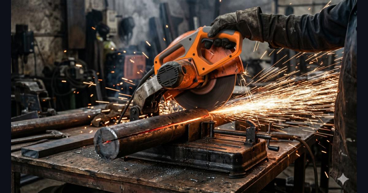
Kerf allowance is the width of material that the cutting tool removes from the bar or plate with every cut. Every time your blade, disc, or plasma arc passes through steel, it converts a thin slice of metal into heat, sparks, and swarf — and that slice of material is permanently gone. If your cut list does not account for it, your pieces come out short.
Key Facts
- Typical site kerf: 3mm for abrasive cut-off wheel (300×3.5mm disc)
- Formula: Total length = Σ piece lengths + (n−1) × kerf
- Tool: Pipe Cut List Optimizer handles kerf automatically →
- Rule: One kerf per cut — not per piece
What Creates the Kerf
The kerf width depends entirely on your cutting tool. An abrasive cut-off wheel removes material equal to its own thickness — a standard 300mm×3.5mm Type 41 resin-bonded disc leaves a kerf of approximately 3mm (the disc wears slightly as it cuts). A bandsaw removes material equal to the blade set width, typically 1.5–2mm. A plasma arc melts and blows away a 1.5–4mm slot depending on amperage and travel speed. An oxy-fuel torch removes 2–5mm depending on plate thickness and preheat.
Kerf allowance cutting — accounting for this lost material — is not optional. It is a basic requirement of any accurate cut list. The IS 2062 dimensional tolerances for structural steel sections are ±0.5mm on length for cut pieces. A 3mm kerf ignored across a 10-piece cut list introduces 27mm of unaccounted loss, which exceeds the tolerance on every single piece.
Typical Kerf Values by Cutting Method
| Cutting Method | Typical Kerf Width (mm) | Notes |
|---|---|---|
| Abrasive cut-off wheel (chop saw) | 2.5–4.0 | Standard 300×3.5mm disc: use 3mm default |
| Cold saw (carbide-tipped) | 2.0–3.0 | Cleaner cut, slower feed; common in tube workshops |
| Bandsaw (bi-metal blade) | 1.5–2.0 | Best for structural sections; cooler cut |
| Plasma cutting (mechanised) | 1.5–3.0 | Depends on amperage and plate thickness |
| Oxy-fuel (gas cutting) | 2.0–5.0 | Wider kerf on thicker plate; allow 3.5mm for 20mm MS |
| Laser cutting (fibre laser) | 0.2–0.5 | Negligible for most cut lists; allow 0.5mm to be safe |
Values are typical workshop ranges. Always measure a test cut if exact kerf is critical to tolerance.
How Kerf Affects Your Cut List
The formula for total bar consumption is:
Total length consumed = Σ(all piece lengths) + (number of cuts − 1) × kerf
The "number of cuts − 1" is the key: the first piece does not require a cut at the bar start (the bar already has a clean end), and the last piece's trailing end is the offcut — no kerf is consumed there. Only the cuts between pieces consume kerf. So if you are cutting 5 pieces from one bar, you make 4 internal cuts, consuming 4 × kerf in addition to the sum of the piece lengths.
Kerf allowance cutting — in Hinglish: "cutting mein kerf kitna hota hai" — is often overlooked when pieces are long relative to kerf. It becomes critical when pieces are short and many cuts come from one bar, because the accumulated kerf loss can add up to the equivalent of one extra piece.
Worked Example: 8 Pieces of 700mm from a 6000mm Bar
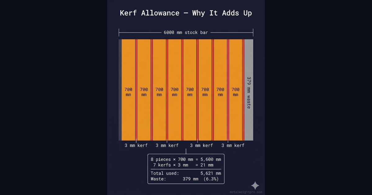
Given: Stock bar = 6000mm. Required pieces: 8 × 700mm. Cutting method: abrasive cut-off wheel, kerf = 3mm.
Step 1 — Sum of piece lengths: 8 × 700 = 5,600mm
Step 2 — Number of internal cuts: 8 pieces = 7 cuts between them
Step 3 — Total kerf consumed: 7 × 3 = 21mm
Step 4 — Total bar consumed: 5,600 + 21 = 5,621mm
Step 5 — Waste (offcut): 6,000 − 5,621 = 379mm
If kerf is ignored: 5,600mm consumed, waste appears to be 400mm — but this is wrong. The actual 379mm offcut is 21mm smaller than expected, because the saw has consumed that material. On a job with 50 bars going through the chop saw, ignoring kerf across 350 cuts consumes 350 × 3mm = 1,050mm of "invisible" material.
Kerf Allowance in the Cut Optimizer Tool
The Pipe Cut List Optimizer has a dedicated kerf input field. Enter your cutting method's kerf width in millimetres (default is 3mm). The tool then deducts one kerf between every consecutive pair of pieces assigned to a bar. It does not deduct kerf at the bar ends — only for internal cuts.
Setting kerf to zero gives the theoretical minimum material — useful to see the best possible outcome and compare with the kerf-adjusted plan. For laser or waterjet cutting where kerf is under 0.5mm, setting it to 0 or 0.5 is accurate enough for most fabrication planning purposes.
Kerf for Pipe and Hollow Section Cutting on Site
For thin-wall tube (1.5–2.5mm wall), fabricators often use a 1.6mm cutting disc on an angle grinder — this leaves a kerf of 1.6–2.0mm. Using the standard 3mm default in the cut list for these cuts overstates the kerf and makes the plan unnecessarily conservative. If your workshop consistently uses a 1.6mm disc on thin-wall CHS, change the kerf input in the optimizer to 2mm.
For heavy-section cutting — say, 100×100×6 SHS on a cold saw — the blade set width is typically 2.5mm. A bandsaw gives 1.8–2mm. In both cases, the default 3mm kerf will overstate the loss by 0.5–1.2mm per cut, which across a large cut list slightly overstates your bar requirement.
Frequently Asked Questions
What kerf allowance should I use for an abrasive cut-off wheel?
For an abrasive cut-off wheel (the standard chop saw disc on Indian job sites), use a kerf allowance of 3mm as your default. This matches the 3.5mm thickness of a standard 300mm×3.5mm Type 41 resin-bonded cutting disc — the disc wears slightly during the cut, so the actual kerf is 3–3.2mm. If you are using a thinner 2.5mm disc on smaller-diameter material, reduce the allowance to 2.5mm. If you are unsure of your disc thickness, measure it with calipers before starting the job. The default kerf in the Pipe Cut List Optimizer is set to 3mm specifically for this scenario.
Does kerf matter for oxy-fuel cutting of thick plates?
Yes — kerf matters significantly for oxy-fuel (gas cutting) of thick plates. The oxy-fuel kerf width ranges from 2mm for thin plates (6–8mm) to 5mm or more for plates above 50mm thickness, because a larger cutting oxygen jet is required for thicker material. If you are cutting multiple pieces from a single plate and your cut list ignores kerf, each piece will come out slightly short. On a 1200mm plate being cut into three 400mm pieces with 4mm oxy-fuel kerf, the third piece would actually measure 392mm — 8mm short — because two 4mm kerfs are consumed but not accounted for.
How does the Pipe Cut List Optimizer handle kerf allowance?
The Pipe Cut List Optimizer has a dedicated kerf input field where you enter your cutting method's kerf width in millimetres. The tool then deducts one kerf width for every cut made within a bar, not at the ends. So for a bar holding three pieces, the tool deducts two kerf widths from the available bar length (one kerf between piece 1 and piece 2, one kerf between piece 2 and piece 3). The default kerf value is 3mm, matching a standard abrasive cut-off wheel. Setting kerf to zero gives the theoretical minimum — useful for waterjet or laser cutting where kerf is under 0.5mm.
What is a typical kerf width for plasma cutting 6mm MS plate?
For mechanised plasma cutting of 6mm MS plate with a standard plasma cutter (Hypertherm Powermax 45 class or similar), the typical kerf width is 1.5–2.5mm depending on cut speed, amperage, and nozzle condition. Hand plasma cutting produces a wider kerf of 2.5–4mm because the torch is less stable. For CNC plasma cutting on a table, use 2mm as a safe kerf allowance for 6mm MS plate. For thicker plates (12–20mm), the kerf widens to 3–4mm. Always measure a test cut on a scrap piece before committing your kerf input to a large cut list.
Put your kerf-adjusted cut list into the optimizer and get a bar-by-bar cutting plan instantly.
Try the Free Pipe Cut List Optimizer →