Fish Mouth Pipe Cut Template: How to Lay Out and Mark
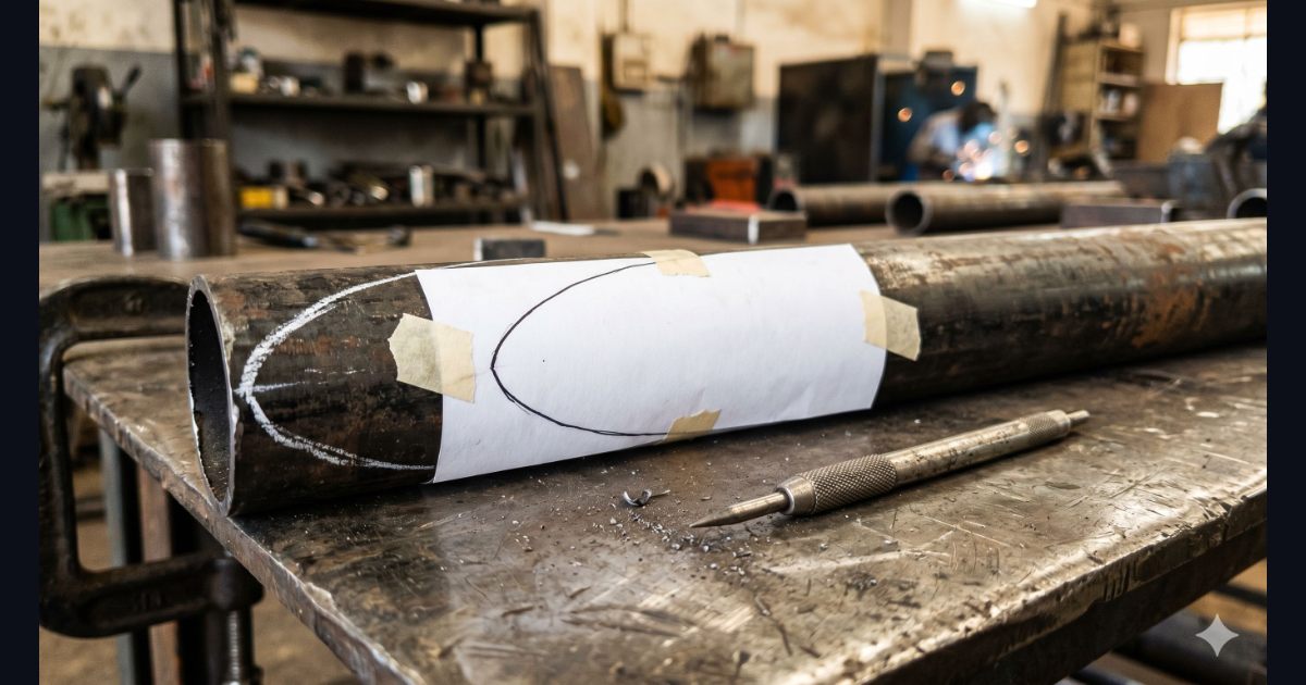
A fish mouth pipe cut template is the paper strip you wrap around the end of a branch pipe to scribe the exact curved line where you need to cut so the pipe fits flush against a larger main pipe. Without it, you are either guessing the profile freehand — which gives a poor fit-up — or grinding repeatedly until the gap closes. With a correctly generated and printed fish mouth template, the first cut lands within 1mm of a perfect fit.
Key Facts
- Template width: π × branch OD (= full branch circumference)
- Profile shape: Sine-like curve — deepest at crown, zero at flanks
- Standard: IS 3589 — OD tolerances for larger pipes affect template accuracy
- Tool: Free Pipe Notching Calculator →
What "Fish Mouth" Means in Fabrication
The term fish mouth comes from what the cut pipe end looks like when you hold it up — the curved opening resembles an open fish mouth, wider at the sides and pinched to a deep point at the top. Fabricators across India use this term on the shop floor; the engineering drawing will often say "saddle cut" or "pipe cope." They all mean the same profile.
Fish mouth cuts appear wherever round pipes intersect: handrail posts meeting horizontal rails, structural CHS bracing members meeting chord pipes, pipe rack branch lines joining headers, and scaffold tube joints. In any of these applications, the branch pipe needs to sit tight against the main pipe before welding — a gap of more than 1.5mm around the joint is a reject condition in most structural welding codes.
What You Need Before You Start
You need three measurements: the outer diameter (OD) of the main pipe, the OD of the branch pipe, and the intersection angle. These three values fully define the cut profile.
The most common mistake is confusing nominal bore (NB) with OD. A 40mm NB pipe has an OD of 48.3mm under IS 1239 — if you enter 40 instead of 48.3, your template will be completely wrong. Always look up the OD from the IS 1239 or IS 3589 standard table, or measure the actual pipe circumference and divide by π.
To measure OD without calipers: wrap a tape tightly around the pipe, read the circumference, divide by 3.1416. A reading of 151.8mm gives OD = 48.3mm — the exact IS 1239 OD for a 40mm NB pipe.
How to Generate the Fish Mouth Template
The quickest method is the free Pipe Notching Calculator. Enter the main pipe OD, branch pipe OD, and join angle. The calculator plots the saddle curve using the formula z(θ) = r_main / sin(α) − √(r_main² − (r_branch × cos θ × sin(α))²) / sin(α) and outputs a printable PDF template scaled to the actual branch pipe circumference.
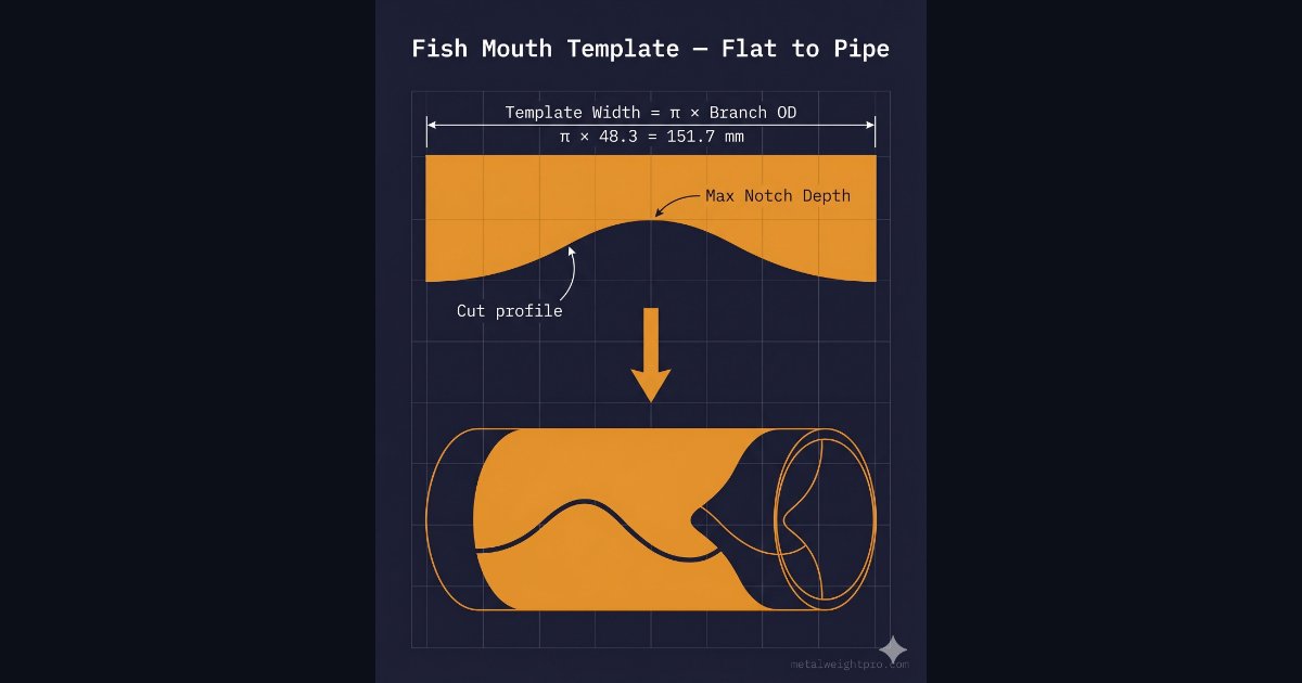
The template is a rectangular strip. Its width equals π × branch OD — the full circumference. Along the bottom edge, the curve is plotted: depth values at each point around the circumference. The deepest point is the crown (the point that wraps to the top of the pipe, directly over the main pipe centreline). The curve returns to zero at the flanks (both sides of the strip).
Worked Example: 48.3mm Branch on 88.9mm Main Pipe at 60°
I recently fabricated a pipe rack where APL Apollo 88.9mm OD CHS (40mm NB Heavy) headers carried 48.3mm OD branch pipes (40mm NB Medium) at 60° — a common angle in raked pipe racks. Here are the numbers.
Given: Main pipe OD = 88.9mm → r_main = 44.45mm. Branch pipe OD = 48.3mm → r_branch = 24.15mm. Angle α = 60° (sin 60° = 0.866).
Template width: π × 48.3 = 151.7mm
Maximum notch depth (acute side, θ = 0°):
z = 44.45 / 0.866 − √(44.45² − (24.15 × 0.866)²) / 0.866
= 51.33 − √(1975.8 − 437.8) / 0.866 = 51.33 − √1538.0 / 0.866 = 51.33 − 39.22 / 0.866 = 51.33 − 45.29 = 6.04mm
Wait — that is the depth on the acute side. On the obtuse side (θ = 180°), the notch actually rises above the pipe end, meaning the branch pipe extends further on that side. The asymmetry is what distinguishes a 60° template from a 90° template: one half of the strip is longer than the other.
Total height difference across the template (i.e., how far the branch end extends on the obtuse side vs. the acute side) = 2 × r_branch / tan(α) = 2 × 24.15 / 1.732 = 27.9mm. This is the vertical shift you see on the printed template.
Verify these values using the Pipe Notching Calculator → — enter OD 88.9, branch OD 48.3, angle 60°, and the calculator plots the full asymmetric profile ready to print.
Step-by-Step Layout on the Pipe
- Print at 100% scale. In your PDF viewer, set print scaling to "Actual size" before printing. A scaled-down template will not match the pipe circumference.
- Verify width. Wrap the strip around the branch pipe — the ends should meet flush. If they overlap or fall short by more than 1mm, recheck your print settings.
- Orient correctly. For angled joints, the template has a longer side and a shorter side. The longer side wraps to the obtuse (far) face of the joint; the shorter side wraps to the acute (near) face.
- Secure with masking tape. Two small pieces at top and bottom. Do not use glue or sticky tape — they slip under scribing pressure.
- Scribe firmly. Use a fine metal scriber, not a marker pen. Press hard enough to leave a clear scratch on the pipe surface. Mark a reference dot at the crown (deepest point) with a centre punch.
- Cut and finish. Cut outside the line with an angle grinder. Finish to the line with a flap disc. Deburr the inside edge with a half-round file.
- Dry-fit check. Place the cut branch pipe against the main pipe and check the gap around the full perimeter. Gap should be under 1.5mm everywhere. If one side is tight, relieve with a flap disc; if one side has a gap, it usually means the print was slightly scaled.
Tips for Accurate Marking on Site
IS 3589 specifies OD tolerances for larger ERW pipes used in water and structural service. For pipes above 100mm OD, the tolerance is ±1%, which can be 1–1.5mm on a 150mm pipe. For a fish mouth cut on a large-diameter pipe, always measure the actual OD rather than trusting the nominal size.
On noisy sites where you cannot easily print — "fish mouth cut kaise karte hain bina print ke?" — fabricators sometimes make the template with a strip of tin sheet, bent to match the pipe circumference and scribed manually. This requires plotting 12–16 depth points by hand using the formula, which is time-consuming but works when printing is not possible.
For weight estimation of the pipes you are joining, the Metal Weight Calculator calculates CHS pipe weight per metre instantly — useful for project material cost estimates and truck loading calculations.
For more detail on the underlying saddle cut formula and how profile changes at non-90° angles, see the Pipe Notching and Saddle Cuts: A Fabricator's Complete Guide →
Frequently Asked Questions
Is a fish mouth cut the same as a saddle cut?
Yes — fish mouth cut and saddle cut are two names for the same operation. 'Fish mouth' is the common workshop and site term across India; 'saddle cut' is the formal term used in engineering drawings and welding procedure specifications. Both describe the curved profiled cut at the end of a branch pipe that allows it to sit flush against the outer surface of a larger main pipe, ready for welding without any significant gap around the joint perimeter.
How do I measure the outer diameter of a pipe if I don't have calipers?
Wrap a flexible tape measure tightly around the pipe and read off the circumference. Then divide by π (3.1416) to get the outer diameter. For example, a circumference of 189mm gives OD = 189 ÷ 3.1416 = 60.2mm — which corresponds to the IS 1239 standard OD of 60.3mm for a 50mm NB pipe. This method is accurate to within ±1mm when the tape is pulled snugly and the pipe is round. Never use the nominal bore size as a substitute for OD — a 50mm NB pipe has an OD of 60.3mm, not 50mm.
Can I use a fish mouth template for rectangular hollow sections?
No. A fish mouth or saddle cut template is calculated using the circular pipe formula and only works for round circular hollow sections (CHS). Rectangular and square hollow sections (RHS and SHS) have flat faces, so when a branch RHS or SHS meets a main member, the cut is a straight cope cut — not a curved profile. The cope cut dimensions are calculated from the face width and the gap allowance, which is a simpler geometry calculation with no trigonometric profile involved.
How accurate does my printed template need to be?
For structural welding, the printed template needs to be accurate to within 1mm in width — any more error and the template will not wrap correctly around the branch pipe circumference. The profile curve accuracy matters most at the crown (deepest point), where a 1mm error in the template translates directly to a 1mm gap at the weld joint. Always verify the printed strip width by wrapping it around the actual branch pipe before scribing — the strip ends should meet with no overlap and no gap. If they don't, recheck your print scale settings in the PDF viewer.
Generate a printable fish mouth template for any pipe size and angle — free, no login needed.
Try the Free Pipe Notching Calculator →